Select your region:

Complex vertical louvre wall
Züblin AG
A bespoke 3D modelled design provides the solution to a complex vertical louvre geometry at the Airport end of Stuttgart’s new rail extension.
The Goal
Rail extension to reduce the journey time to the airport
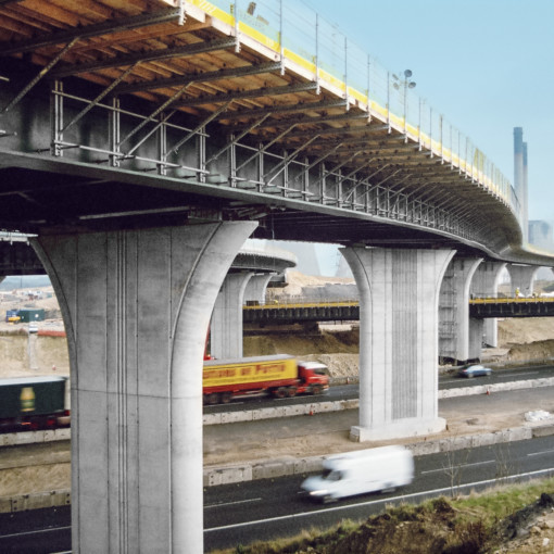
The new extension was designed to cut the journey time between Stuttgart city centre and the airport to only 30 minutes.
The Project
Summary:
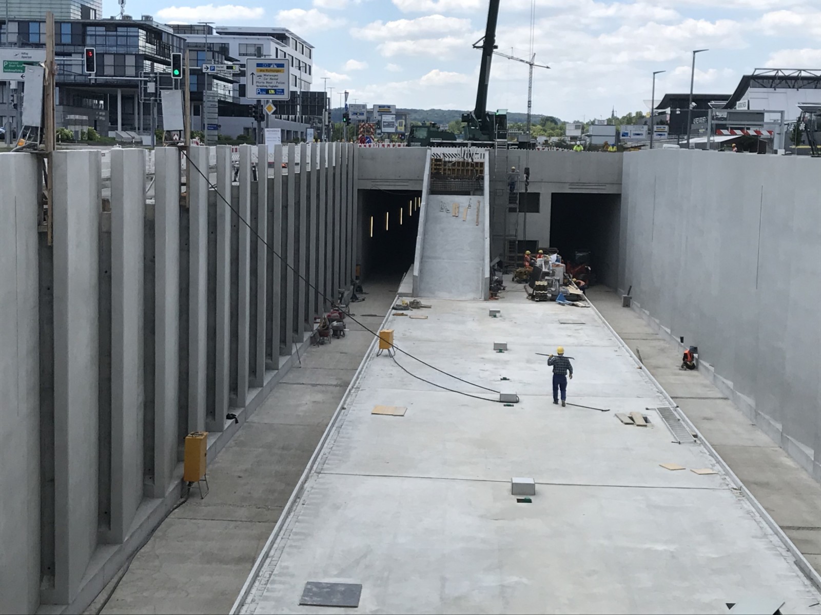
The three-kilometre extension for the U6 line of Stuttgart’s Stadtbahn light rail system was designed to offer passengers a direct link from Gerlingen in the north-west of the city to the airport in the south.
Challenge:
When Zublin was awarded the contract for the ramp, tunnel and terminus structure at Stuttgart Airport, they soon realised that one of the biggest challenges would be to build a highly complex vertical louvre wall. This architecturally idiosyncratic wall structure – located at the Airport/Exhibition Centre terminus – required MEVA’s expert design team to create a bespoke 3D design solution.
The Solution
- Exacting 3D modelling
MEVA’s engineers started by converting an undimensioned initial sketch from the tendering procedure into a detailed 3D model showing the exact angles, niches and spacings.
- Planning a bespoke formwork solution
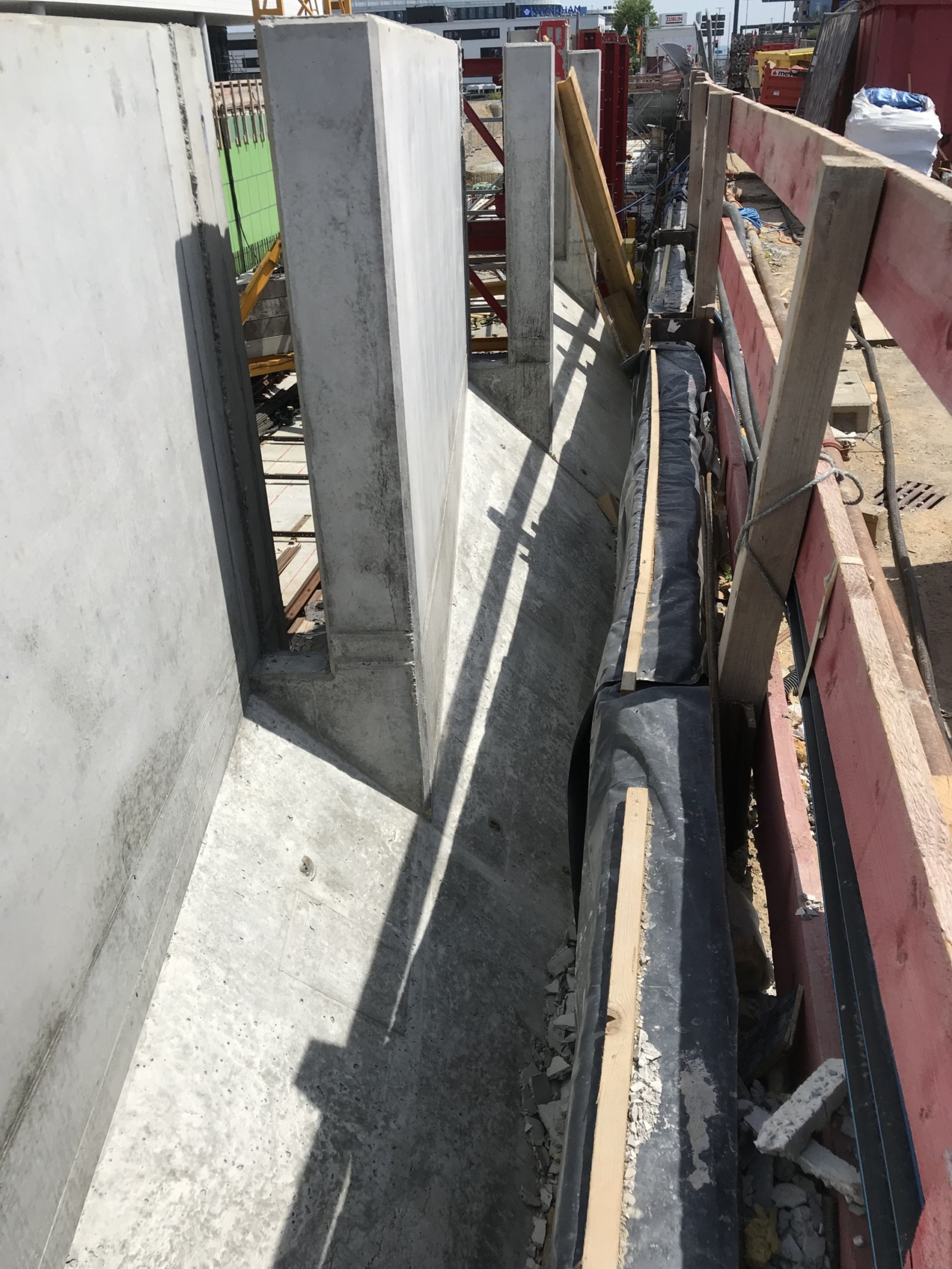
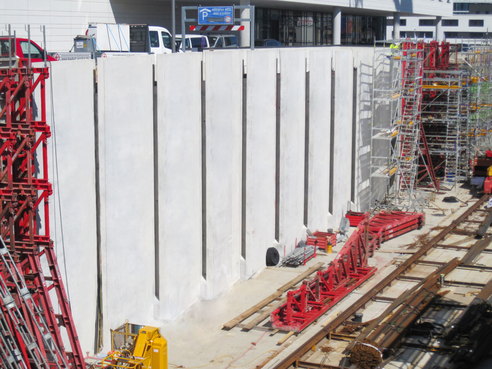
Rising to a height of up to 9.30m, the vertical louvre wall heights vary in response to a nearby footpath and cycle track. The composition features an overlapping sequence of 4m wide louvres. The walls project at the top and are tapered in thickness – a narrowing effect achieved by the rear face formwork. To speed up and streamline site operations, provision was also made for interlinking the special formwork panels.
- From the bottom up
A total of 18 pour cycles were required to build the complex vertical louvre walls. The elaborate geometry was already reflected in the steel fixing operations – the shape of the louvre walls being traced out by the precise reinforcement layout at ground level. 15cm high kickers were then cast to simplify the subsequent assembly of the tall formwork units and support frames.
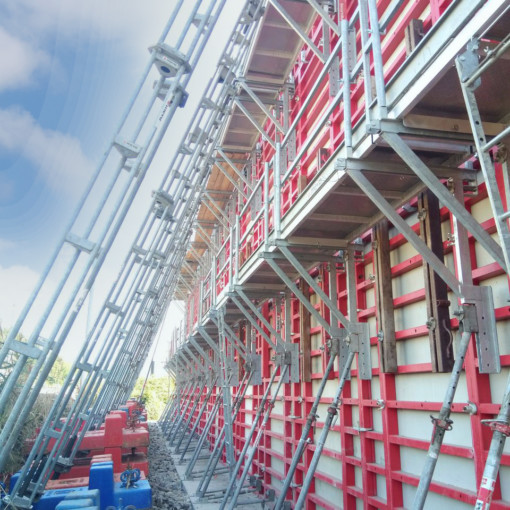
- Specially-designed, three-part formwork
To achieve the required overlapping configuration with single-sided formwork, a special solution was needed to form the gaps between the individual louvres. This function was performed by a MEVA-designed niche formwork assembly that allowed efficient and straightforward creation of the required geometries.
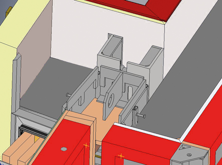
A niche kicker was also required at ground level to take account of the varying angles formed with the joints between the precast-concrete track blocks. Then, as the largest of the three units, came the front niche formwork. Given the spatial constraints, the team opted for a steel assembly.
- Reliable positioning between the louvres
First, the special formwork is screwed through the frame to the front wall formwork. Tight-fitting timber board is then incorporated into the boxout to resist the fresh concrete pressure. A special L-shaped metal bracket is also fitted into the niche formwork, with the longer leg secured to the frame of the louvre formwork. In case of differences in pour height and fresh concrete pressures between two louvres, this provides horizontal stability by transferring the pressure to the frame.
- Simple, smart stripping and removal
To facilitate removal of the niche formwork after casting, it is additionally fitted with hinged corners and designed with a trapezoidal shape with a narrower rear face. As a result, once the front part is free, the unit can be easily removed without friction. The hinged corners also allow the sides to be folded in, which further simplifies the stripping process.
- Managing a north-south divide
The vertical louvre walls exhibit varying geometries on the northern and southern sides: the louvres are arranged in opposing directions and the rear-side taper also differs in response to the adjacent landscaping. The special shapes necessitated the use of custom-designed precision formwork that can be reused as the works progress.
Our procedures vary according to the area we’re working in. At the start, this required extreme concentration. But we got the hang of it after we’d done it two or three times. And you soon notice how MEVA’s designs are geared to on-site practice and making operations as easy as possible.
explains Züblin site manager Heiko Wagner, referring to the additional complication of the north/south difference.
- Combining single and double-sided solutions
The use of single-sided formwork was not possible over the full height, so MEVA’s experts developed an intelligent solution to combine single- and double-sided operations. The STB 450 support frame and Mammut 350 heavy-duty formwork are used to cast the lower section against the pit wall. Here, the system’s ability to accommodate fresh concrete pressures of up to 100kN/m² over the full surface is particularly beneficial as unlimited pour speeds are possible for heights of up to 4m.
The single-sided area of the northern wall is also larger and is supported by three Triplex braces to resist the accordingly higher forces. The southern wall, on the other hand, only needs two of MEVA’s modular heavy-duty braces. In the upper part of the vertical louvre walls, single-sided is replaced by double-sided formwork.
- A smooth finish
To achieve extra-smooth and uniform concrete surfaces, the special formwork was fitted with alkus all-plastic facings at the MEVA plant. The facings were screwed down from behind to avoid screw marks on the surface. Joints and angles were welded with the same synthetic material used for the facings. This prevents the escape of cement paste and thus delivers very high-quality results.
The Outcome
MEVA’s proposal to work with a steel frame paved the way for a formwork assembly that essentially amounted to two single-sided arrangements. The absence of tie holes with this solution automatically eliminated the need for blank cones, thereby vastly simplifying and speeding up operations. It also allowed the achievement of a more even and uniform surface finish.
Featured Products
- Mammut 350 wall formwork
- STB 450 support frame
- Triplex heavy-duty brace
- Special design
Client:
Züblin AG
Project:
Vertical louvre walls at Airport/Exhibition Centre
Location:
Light rail terminus, Stuttgart, Germany
Principal:
Stuttgarter Straßenbahnen AG (SSB)
Engineering & Support:
MEVA Schalungs-Systeme GmbH, Haiterbach, Germany
Got any questions about this topic?
Why not get in touch, we are here to help you.
If you want to know more about this or any other projects please use the contact form to get in touch, we would love to hear from you.
For contact details specific to this region, visit the contact us page to find out more.